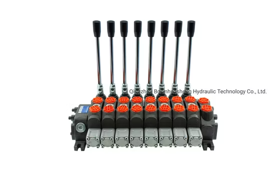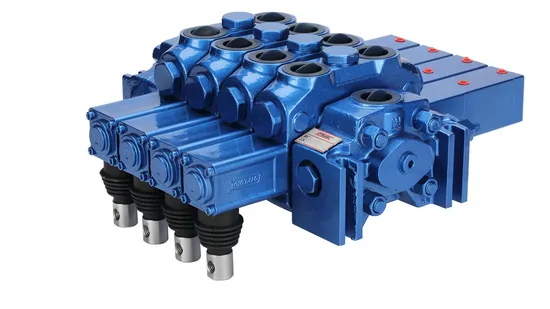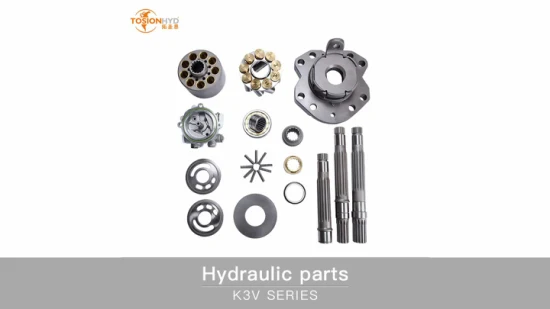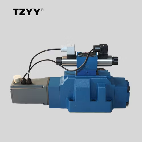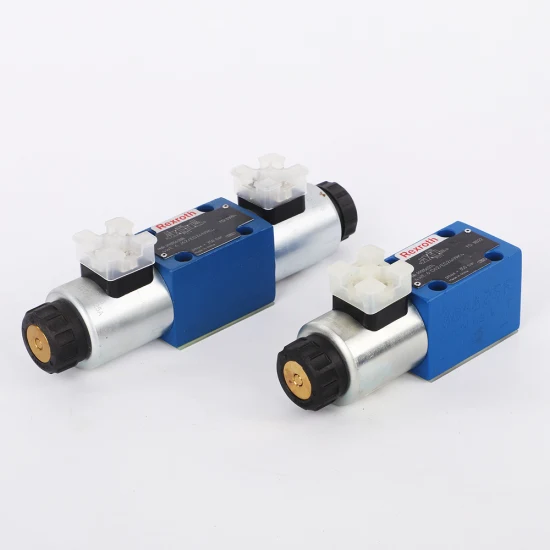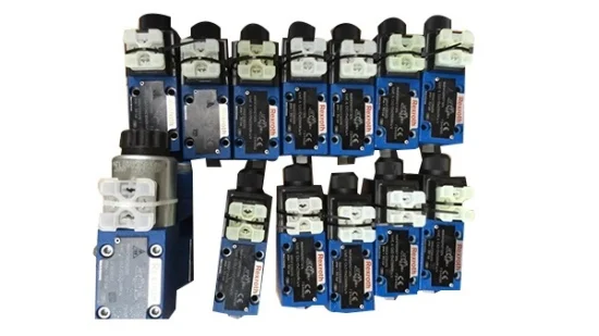
Rexroth Hydraulic Direct Control Valve of 4we6 4we10 4wh 4we3 4we4 12V/24V Solenoid Directional Valve/Pressure Reducing Valve/Loader Valves/Back Pressure Valve
Description
Basic Info.
| Model NO. | 4WE6E |
| Pressure | Ordinary Temperature |
| Valve Structure | Pilot Piston Structure |
| Power Supply | AC Solenoid Valve |
| Usage | Safety, Emptying, Drain, Temperature Control, Flow Control |
| Standard | GB |
| Application | Industrial Usage, Water Industrial Usage, Household Usage |
| Warranty | 12 |
| Lead Time | 5 |
| Color | Blue |
| Transport Package | Carton |
| Specification | 20*15*10 |
| Trademark | Rexroth |
| Origin | Ger |
| HS Code | 8413606090 |
| Production Capacity | 2000/Weeks |
Product Description
Rexroth hydraulic valve 4WE6 4WE10 4WE6E/62EG24N9K4 solenoid directional valveProduct Description
4/3-, 4/2- or 3/2-way versionPorting pattern according to ISO 4401-03-02-0-05 (withor without locating hole) and NFPA T3.5.1 R2-2002 D03High-power solenoid, optionally rotatable by 90°Electrical connection as individual or central connectionManual override, optionalSpool position monitoring, optionalCE conformity according to the Low-Voltage Directive2014/35/EU for electrical voltages > 50 VAC or> 75 VDCSolenoid coil as approved component with UR markingaccording to UL 906, edition 1982, optionalApproval according to C22.2 No. 139-1982, optional
The directional valves of type WE are solenoid-actuated directional spool valves that can be used as electro-magnetic component. They control start, stop and direction of a flow. The directional valves basically consist of the housing (1), one or two electronic solenoids (2), the control spool (3), and the return springs (4). In the de-energized condition, the control spool (3) is held in the central position or in the initial position by the return springs (4) (except for version "O"). If the wet-pin electronic solenoid (2) is supplied with power, the control spool (3) moves out of its rest position into the required end position. In this way, the required direction of flow according to the selected symbol is released. After the electronic solenoid (2) has been switched off, the control spool (3) is pushed back into its central position or into its initial position (except for valves with "OF" detent and valves without type "O" spring). A manual override (5) allows for the manual switching of the valve without solenoid energization. For unobjectionable functioning, the hydraulic system has to be bled properly. Without spring return "O" (only possible with symbols A, C and D) This version is a directional valve with two spool positions and two electronic solenoids without detent. The valve without spring return at the control spool (3) has no defined basic position in the de-energized condition.
general
Size | 6 | ||
Weight | Valve with one solenoid | kg | 1.45 |
Valve with two solenoids | kg | 1.95 | |
Installation position | any | ||
Ambient temperature range | NBR seals | °C | -20 … +50 |
FKM seals | °C | -15 … +50 | |
Version for HFC hydraulic fluid | °C | -20 … +50 | |
Low-temperature version 1) | °C | -40 … +50 | |
Storage temperature range | °C | +5 … +40 | |
MTTFD values according to EN ISO 13849 2) | Years | 300 | |
| 1) | For the use at low temperatures, see Project planning information |
| 2) | For further details, see data sheet 08012 |
| Quantity(pieces) | 1 - 5 | >5 |
| Lead time (days) | 10 | To be negotiated |

Prev: Blince 5p40 40L/Min Hydraulic Multi
Next: Bm5 Eaton Orbit Motor Bm5 BMS Series 2K Hydraulic Disc Valve Gerolor Motor
Our Contact


